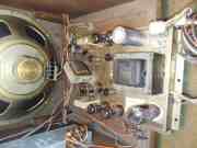
Motorola B1000W Stereo Table Radio

Discussions about radios and tuners. Do you have an old radio that is giving you fits? This is the place to talk about them, along with stand-alone radio tuners, tube and solid state, stereo and mono.
User avatar
William
Global Moderator
Posts: 5461
Joined: Fri Jul 09, 2021 12:42 pm
Location: Hart, Michigan
Contact:

Motorola B1000W Stereo Table Radio

Post: # 5192Post William »

Since I'm kind of caught up with things on the bench, I was trying to decide what to do next. Besides shovel snow. :roll: As I looked at my pile of stuff that needs restoration I decided on the Motorola radio I picked up in Arizona 4 years ago. I saw it on Phoenix Craig's list and thought it was cool, and, cheap which is my middle name. I called the guy, he still had it and said if I came today he would sell it to me for even less. My response, I'm on my way. It turns out this is quite the radio, and, from what Dave (Motorola Minion) told me they are kind of rare. It was, and had been, sitting in their garage for what he thought was at least 10 years. The power cord was as stiff as a board from all the heat. Fortunately, all the wiring under the chassis was ok. I gave it a bath before leaving AZ, I wanted to get all the dust bunnies and dead scorpions cleaned out. Once home back in Michigan, I fired it up on the ole' Variac and believe it or not it played. From there it went to a shelf in the basement and has been there ever since.

Now on the bench and chassis pulled from cabinet I can get the big picture. This thing seems to be well built. Lots of caps and resistors to go thru and test. Of course I will replace the electrolytic and film/paper caps, and, resistors as needed. I have already tested the tubes and they are all good, and, all labelled Motorola.

The first thing I did was make a listing of all 66 resistor so I could keep a log of my findings as I tested them. Next, was to replace the power cord and add a fuse. I also replaced one of the film/paper caps which was right there and in the way. I have also checked a few resistors, and, so far they were all within specs. That's it so far, stay tuned. Here are a few photos of what it looks like:

Bill
Attachments
image.jpeg
image.jpeg
image.jpeg
image.jpeg
image.jpeg
User avatar
electra225
Site Admin
Posts: 9026
Joined: Thu Jul 08, 2021 7:48 pm
Location: San Tan Valley, AZ
Contact:

Re: Motorola B1000W Stereo Table Radio

Post: # 5194Post electra225 »

I remember that radio now. You showed it to me when you bought it here in the Phoenix area. I'd replace all the caps except the ceramics. Those rarely cause trouble. The brown ones and the round ones are paper. That is my two cents, perhaps someone has a different idea that will help. Good luck with your project. You sure do take nice pictures. :)
I haven't failed. I've just found 10,000 ways that won't work.....Thomas Alva Edison
User avatar
electra225
Site Admin
Posts: 9026
Joined: Thu Jul 08, 2021 7:48 pm
Location: San Tan Valley, AZ
Contact:

Re: Motorola B1000W Stereo Table Radio

Post: # 5203Post electra225 »

After you replace the filter caps and install a fuse, maybe a good idea would be to get a baseline on it with the Kill-A-Watt installed. This may give you a place to start if you run into an issue. You won't have to wonder if it was something you did or if it existed before you worked on it. This not to besmurch your abilities, but to keep from chasing your tail trying to find a ghost. That chassis has cathode bypass components on the output tubes which should be considered also.
I haven't failed. I've just found 10,000 ways that won't work.....Thomas Alva Edison
User avatar
Motorola minion
Anchor Member
Posts: 854
Joined: Sun Jul 11, 2021 2:23 pm
Location: Central PA
Contact:

Re: Motorola B1000W Stereo Table Radio

Post: # 5251Post Motorola minion »

I was a bit slow to see this Bill. I can't claim any snow heading to the beginning of mud season, after the groundhogs had their say and subsequent speculation, I say it will be partly muddy for 6 weeks at least. I am inside due to sub-optimal garage and barn with cold winds keeping them chilly.

Every time I work on "something batwing" like this awesome AND rare unit, its a pleasant surprise :) simply because I'm not staring at a dozen wax-bombs, before even trying a power-up!!!. I'm reminded that Zenith sold most of the radios and they usually need more caps than a similar Motorola. Other makes of bigger table radios are seldom seen, other than GE and RCA. GE used fewer parts, RCA used way more and usually crappy wax caps and crummy resistors than even Philco and Magnavox. Not all the Electrolytic caps were reform-friendly like most Mallory (240 code), but I most times change them anyway. I even found some 232 caps made by Mag were often still OK.

This Motorola probably has a 322-Tung Sol, 274-RCA or other OEM tube mfr. Those are rarely weak, much less gassy or shorted. No surprise it worked :D If it were mine and I wanted to begin using it, verify the ESR is OK on the electrolytics and let them be if they don't get warm after being on an hour. Adding a 1.5 - 2 amp line fuse is a great idea.

If you were restoring it for a customer or to gift/sell, I definitely would replace the electrolytics. That little gray one and the paper covered electrolytic could be "bridged" to test if they even need replacing. I would also tighten all the wafer style tube sockets, squeeze the contacts together, use contact cleaner on both tube and socket if its a molded black socket, since these cant really be tightened.
User avatar
William
Global Moderator
Posts: 5461
Joined: Fri Jul 09, 2021 12:42 pm
Location: Hart, Michigan
Contact:

Re: Motorola B1000W Stereo Table Radio

Post: # 5259Post William »

Thanks for the good advice, Dave. It sounds like Motorola used quality components. I will test and replace as necessary. The little bit that I played it, it sounded good.

Bill
Firedome
Anchor Member
Posts: 1615
Joined: Sat Jul 10, 2021 1:21 pm
Location: nowhere
Contact:

Re: Motorola B1000W Stereo Table Radio

Post: # 5308Post Firedome »

I've heard of tightening up molded black sockets by using a dental pic, but never tried it myself.
User avatar
William
Global Moderator
Posts: 5461
Joined: Fri Jul 09, 2021 12:42 pm
Location: Hart, Michigan
Contact:

Re: Motorola B1000W Stereo Table Radio

Post: # 5317Post William »

I wonder how that would work?

Bill
User avatar
Motorola minion
Anchor Member
Posts: 854
Joined: Sun Jul 11, 2021 2:23 pm
Location: Central PA
Contact:

Re: Motorola B1000W Stereo Table Radio

Post: # 5646Post Motorola minion »

I do not try to do much with molded sockets, though they are way better at catching dirt that wafer sockets, I soak them with DeOxit and plug the tube in and out a few times. These make for loud crackles when you rock the tubes around, which means you need to do it all again. They do respond well to one application and tightening them is not easy since you cant actually access the crimp that grips the tube pin without actually unsoldering the tube lug and pulling it out the top.

The wafer sockets just beg retightening but don't wrangle them around much or you'll add more labor for yourself replacing the socket, highly recommended.
Firedome
Anchor Member
Posts: 1615
Joined: Sat Jul 10, 2021 1:21 pm
Location: nowhere
Contact:

Re: Motorola B1000W Stereo Table Radio

Post: # 5660Post Firedome »

I've heard of using a dental pic to tighten tube pin sockets, anyone tried that method?
User avatar
William
Global Moderator
Posts: 5461
Joined: Fri Jul 09, 2021 12:42 pm
Location: Hart, Michigan
Contact:

Re: Motorola B1000W Stereo Table Radio

Post: # 6596Post William »

The Motorola B1000W has been on the bench for sometime now. I finally got the parts needed, have them installed, and noticed my dial light bulbs were burned out, and, I also noticed the neon stereo indicator light was not working. The dial light bulbs are easy to test and change, but how do you test a neon bulb? I looked online and all I got was confused. I'm not sure if the bulb is bad or it's something in the circuit that feeds it? It looks like it gets it's feed from L15 in the schematic. It has a 6.8M and a 56K resistor in the circuit. Here's a photo of that part of the circuit.

Thanks, Bill
Attachments
image.jpeg
User avatar
hermitcrab
Anchor Member
Posts: 1504
Joined: Mon Jul 12, 2021 2:49 am
Location: Tri Cities Mich
Contact:

Re: Motorola B1000W Stereo Table Radio

Post: # 6606Post hermitcrab »

Have you checked the voltages?... not sure about this one , but some stereo indicators are more current driven than voltage...do you have the specs of the bulb? neons come in many different voltages...
User avatar
electra225
Site Admin
Posts: 9026
Joined: Thu Jul 08, 2021 7:48 pm
Location: San Tan Valley, AZ
Contact:

Re: Motorola B1000W Stereo Table Radio

Post: # 6609Post electra225 »

Check voltage at pin 1 of L15. It is listed at 120 volts. Then see if you have voltage on R39, the 56K resistor. Check R39 for correct value. If you have voltage, the bulb has to be bad. I don't remember ever having to check a neon bulb. Hopefully someone can help out on that one. Nice job so far, Bill. I'd say if the radio works, you could heavily suspect the bulb as being out.
I haven't failed. I've just found 10,000 ways that won't work.....Thomas Alva Edison
User avatar
hermitcrab
Anchor Member
Posts: 1504
Joined: Mon Jul 12, 2021 2:49 am
Location: Tri Cities Mich
Contact:

Re: Motorola B1000W Stereo Table Radio

Post: # 6631Post hermitcrab »

Check R 35 off the grid of the oscillator as well... it might have drifted up?
User avatar
William
Global Moderator
Posts: 5461
Joined: Fri Jul 09, 2021 12:42 pm
Location: Hart, Michigan
Contact:

Re: Motorola B1000W Stereo Table Radio

Post: # 6648Post William »

Thanks, guys! I did test both resistors and like pretty much all resistors in this thing they are almost dead on. I figured out how to test voltage leading up to the bulb. One side has 119 volts and the other 198 volts. With that test, I determined the bulb was the culprit. Now, to find a bulb.


Bill
User avatar
TC Chris
Anchor Member
Posts: 3743
Joined: Tue Jul 13, 2021 3:50 am
Location: Traverse City, MI
Contact:

Re: Motorola B1000W Stereo Table Radio

Post: # 6686Post TC Chris »

Put a voltmeter across it and see if the voltage varies? The idea of the neon bulb was that when the voltage across it fell below a threshold it would go off, not fade like an incandescent.

Chris Campbell
User avatar
William
Global Moderator
Posts: 5461
Joined: Fri Jul 09, 2021 12:42 pm
Location: Hart, Michigan
Contact:

Re: Motorola B1000W Stereo Table Radio

Post: # 6691Post William »

Chris, when I put a volt meter across it I do not get a reading.

Bill
User avatar
hermitcrab
Anchor Member
Posts: 1504
Joined: Mon Jul 12, 2021 2:49 am
Location: Tri Cities Mich
Contact:

Re: Motorola B1000W Stereo Table Radio

Post: # 6701Post hermitcrab »

pull the bulb out of the circuit and measure the current across it while tuning the set to see if that varies, then you can be sure the bulb is dead
User avatar
electra225
Site Admin
Posts: 9026
Joined: Thu Jul 08, 2021 7:48 pm
Location: San Tan Valley, AZ
Contact:

Re: Motorola B1000W Stereo Table Radio

Post: # 6707Post electra225 »

I appreciate the tips on how to check a neon bulb. Might I impose on one of you to add a blurb about how to check a neon bulb in "Getting Started"? It would be good information to have on hand.
I haven't failed. I've just found 10,000 ways that won't work.....Thomas Alva Edison
User avatar
William
Global Moderator
Posts: 5461
Joined: Fri Jul 09, 2021 12:42 pm
Location: Hart, Michigan
Contact:

Re: Motorola B1000W Stereo Table Radio

Post: # 6709Post William »

Thanks, Elton, I will try that.

Bill
User avatar
Motorola minion
Anchor Member
Posts: 854
Joined: Sun Jul 11, 2021 2:23 pm
Location: Central PA
Contact:

Re: Motorola B1000W Stereo Table Radio

Post: # 6713Post Motorola minion »

Most of the neon lamps are NE-2, which don't light with less than 70 volts. A resistor is normally in series to limit current, which is only 0.3 mA.

I checked my Motorola service manual for the SKR-151, using a similar FM-mpx tuner. The indicator is simply listed as NE86, with a Motorola part number. It is rated at about the same voltage but 1.3 mA instead of .3, and across a 560K resistor.

There is a 200 volt supply feeding through a 56K resistor, then 6.8 meg to the 38 KC doubler transformer (like an IF transformer), so that when the 19 KC pilot is detected, amplified and doubled, there will be current flow through the 6.8M resistor, increasing voltage drop across it, such that the lamp in parallel will glow.

I would ground the transformer side of the 6.8 M resistor and see it the lamp glows, since the 56K will limit current through through the neon lamp.
Post Reply

Who is online

Users browsing this forum: No registered users and 18 guests